I do a lot of medium and small sized welding projects in my shop. The operation of cutting off parts from stock material is of interest to me. I have tried small and large abrasive cutoff saws, and small medium and large horizontal bandsaws. I have heard about cold saws and how they cut accurately and cleanly with no need to debur afterwards. This would have saved me a lot of time building stainless cable railings where I had to cut lots of pieces of steel tube and the ends had to be deburred on the inside, an arduous task.
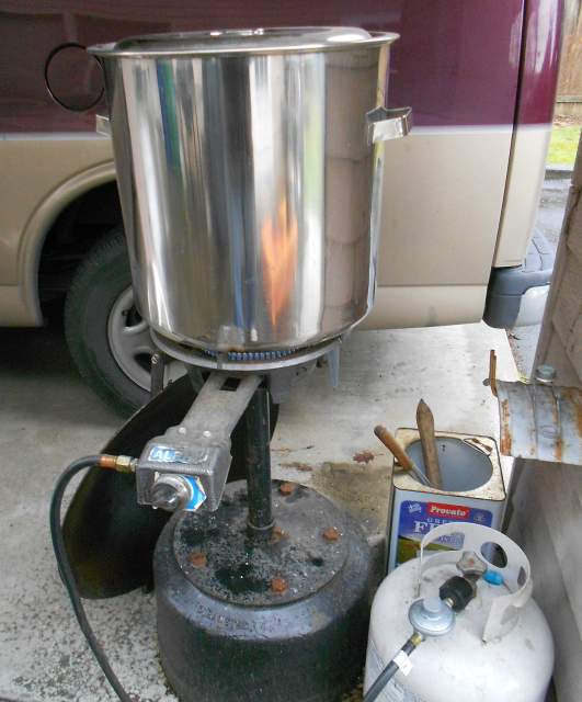
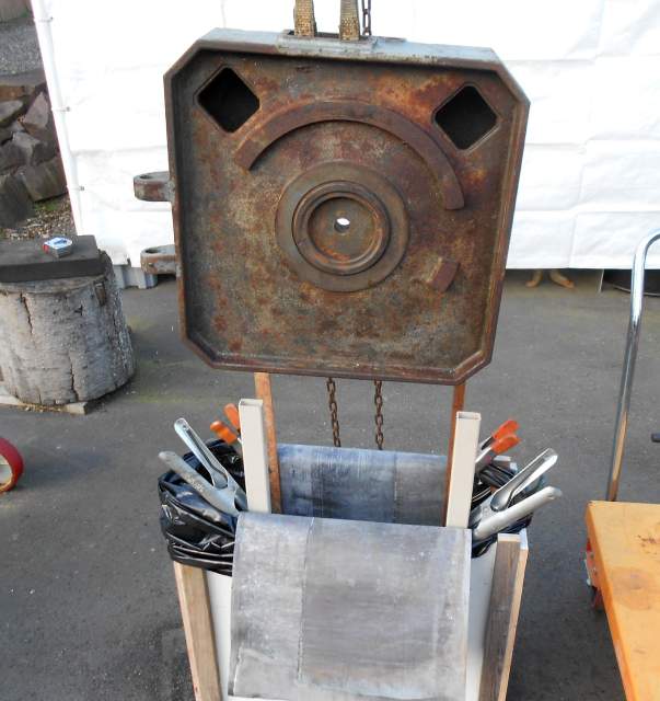
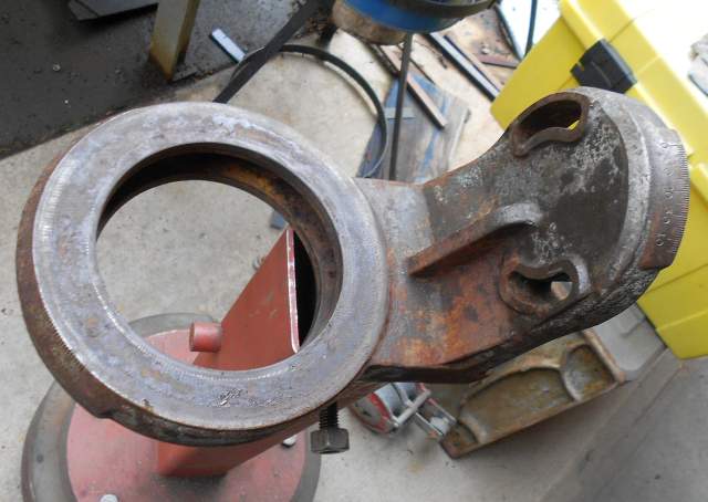
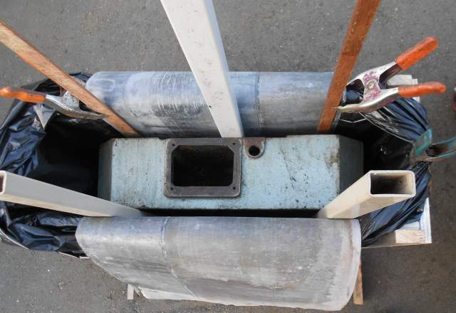
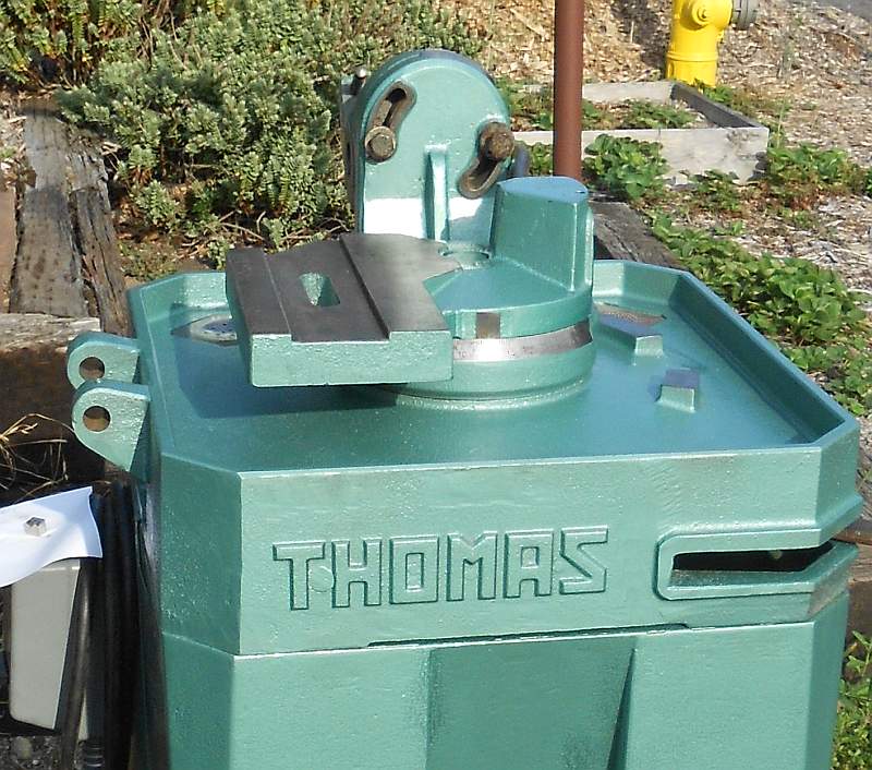
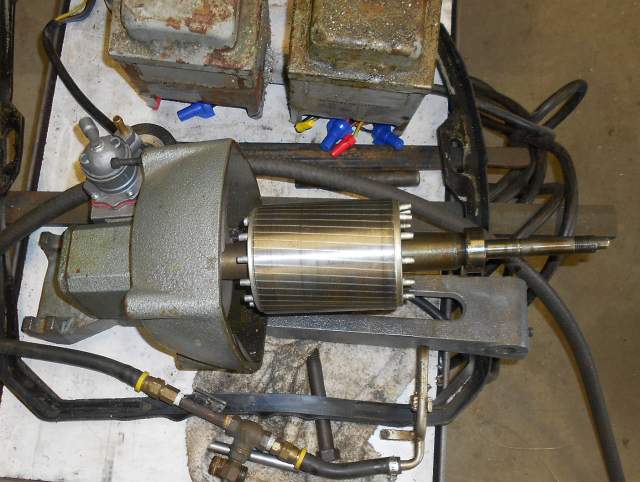
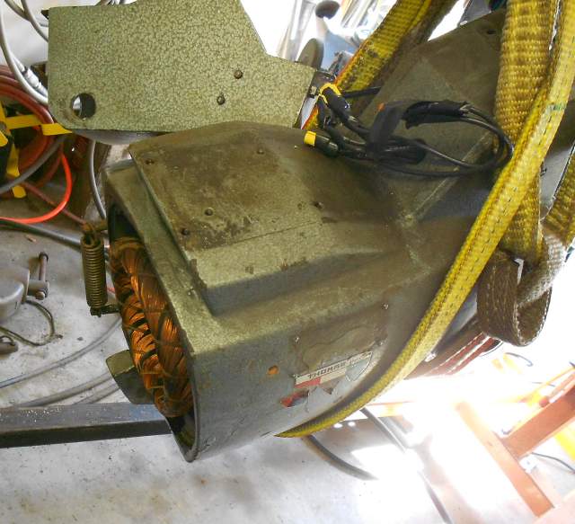
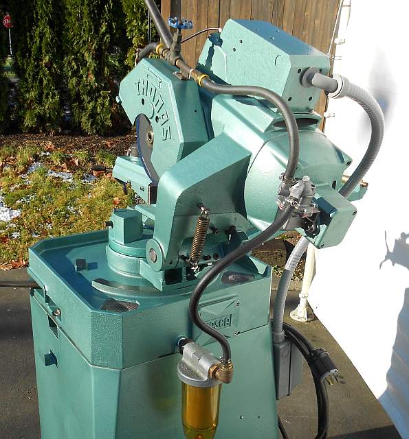
Some time ago I obtained an old Italian cold saw. From my Internet readings I knew to beware of old Italian cold saws. The knock on them was that the gearboxes often wore out. Still, the price on this saw was quite compelling, even if it was obvious the saw needed a lot of work. So I hauled it home and waited until I had a chunk of time available as I knew this restoration would take awhile. Here is a shot of the machine as I received it. I apologize for the lifting strap and the busy background - I'm really not much of a photographer!

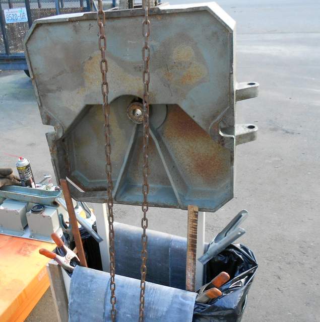
As you can see, the saw was covered in dried-on coolant, old chips, and rust. The reason the lifting strap is there is that as is the machine was very difficult to pick with a single overhead hook. I resolved early on that one of my goals would be to set up the machine so it would be much easier to move. At any rate, beyond the saw's cosmetics there were ominous signs. The blade could be moved by hand through at least 45 degrees of arc. Excessive backlash indeed. Also, the saw is wired 440 VAC only, with a 2-speed motor. As received it had two 1 kVA transformers wired in open delta, bolted to the back of the stand . Being on the back of the machine base, these transformers were covered in filth and chips. Although the saw is supposed to be easy to move to different angular configurations, the vise and swivel castings were corroded and also "glued" with dried-on coolant. At any rate they could only be moved with great difficulty. These problems were all easily seen from the outside. I would find more problems later as I got into the machine.
The first step, of course, was to take things apart. Off came the hideous gray VFD box and the external transformers. Off came the vise and the swivel castings and the saw head. I removed the saw's base from the machine stand. I disassembled the vise and prepared for cleaning and derusting the castings. This is old standard stuff which is routine for anyone who restores machinery but in case you are curious here are some details of how I went about it.
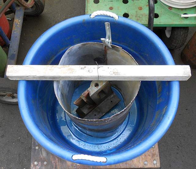
The first step is to get any loose paint and all of the filth and any dirt off of the castings. I did this in two steps. First I sprayed each casting with industrial detergent and let the detergent work for about 20 minutes. Then each casting was pressure washed. This removed a lot, but left a lot of really stubborn dirt. I dealt with this by putting each casting into a stainless pot filled with water and dishwashing detergent, and heating the pot over an outdoor turkey fryer burner. Here is a shot of my hot bath setup:
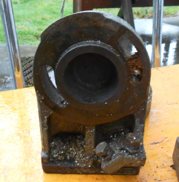
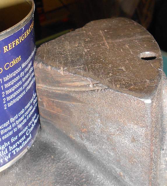
Here are some rather gruesome pictures of the dirty rusty castings:
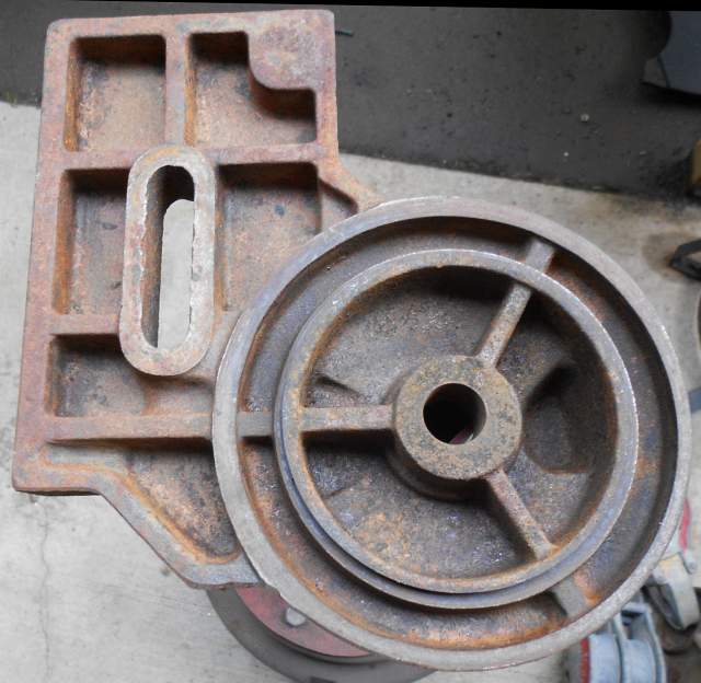
Just so you can see the difference, here are some shots of these castings after degreasing:
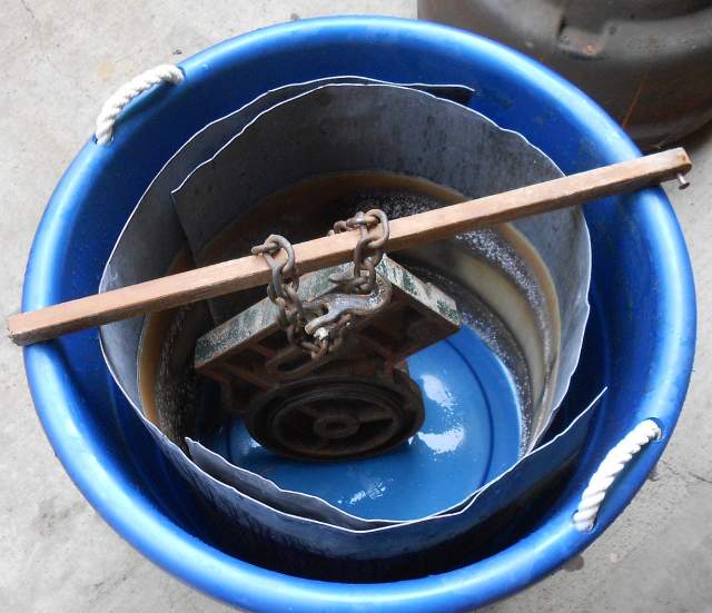
If I'd had a bead blasting cabinet available the next step would be easy. That's going to have to wait for a future project though. I used the electrolytic derusting technique (EDR) for these castings. Many of these castings fit inside a big plastic bucket.
The saw base casting, though, did not. For that casting, I built a box frame from scrap plywood. I made it waterproof by draping a 3 mil plastic bag over it. The base doesn't hang quite straight from the hook so I put some non-conducting standoffs against the electrodes to keep the part from shorting.
For electrodes I like to use sheet lead. I use washing soda and water for a solution. I bought a nice DC power supply which really makes EDR easy. Note that the base casting contains a coolant sump which was very rusty inside indeed. I don't have any pictures of it, but in addition to the big lead sheet electrodes I used a smaller electrode hung down inside the coolant sump. Here are some pictures of the derusting process on the saw base casting:

So you can see how effective the electrolytic derusting process is, here are images of the base casting before and after derusting:
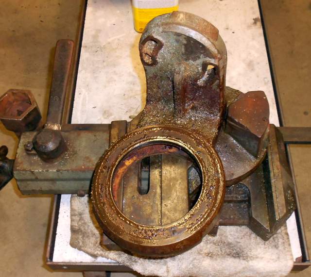
After the degreasing and derusting steps, only a tiny amount of manual cleanup with a wire brush was necessary. With the heavy cleaning on the castings done, I wiped them down with paint thinner and blew them dry, then masked and painted. I used Hammerite green, vaguely similar to the original paint. The saw's sheet metal stand I also cleaned (but didn't derust) and painted. Here are some pictures of the vise after painting:
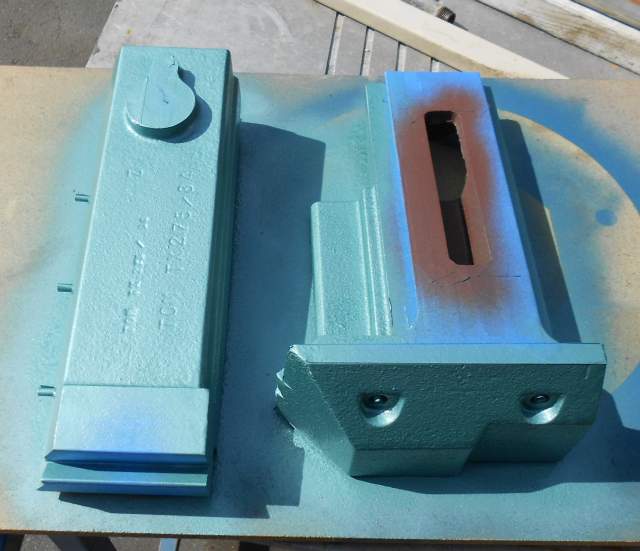
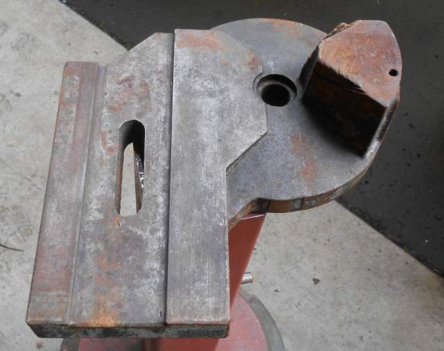
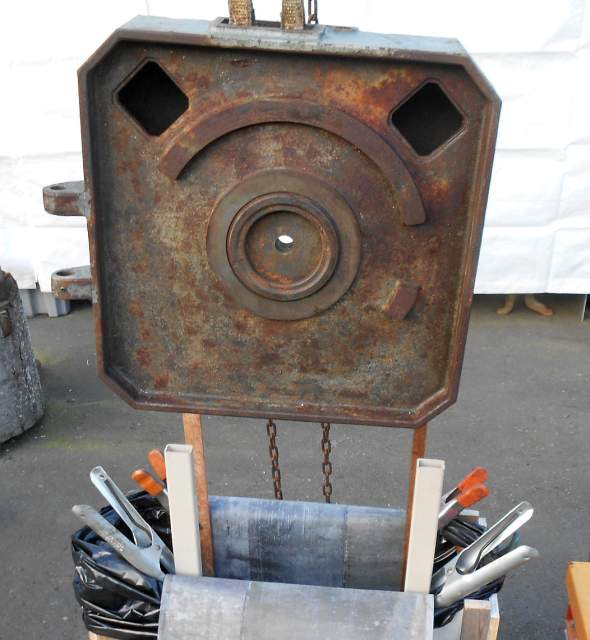
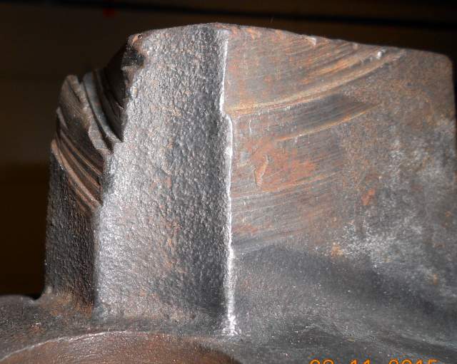
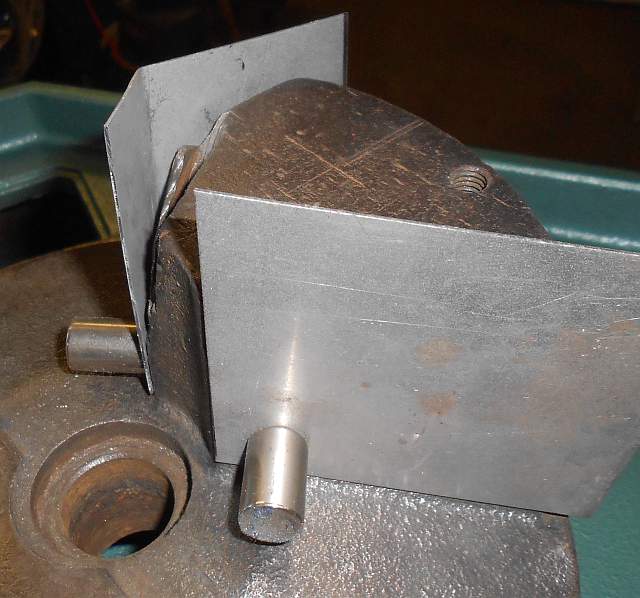
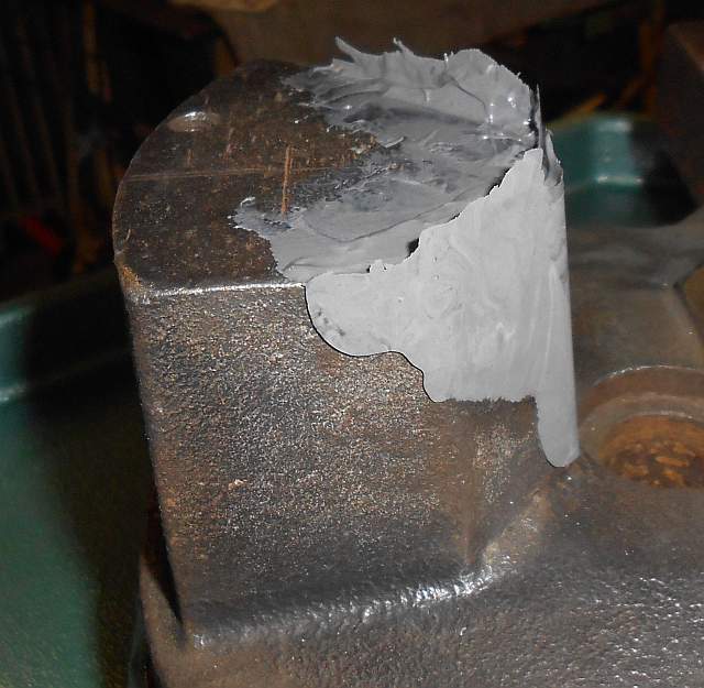
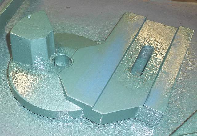
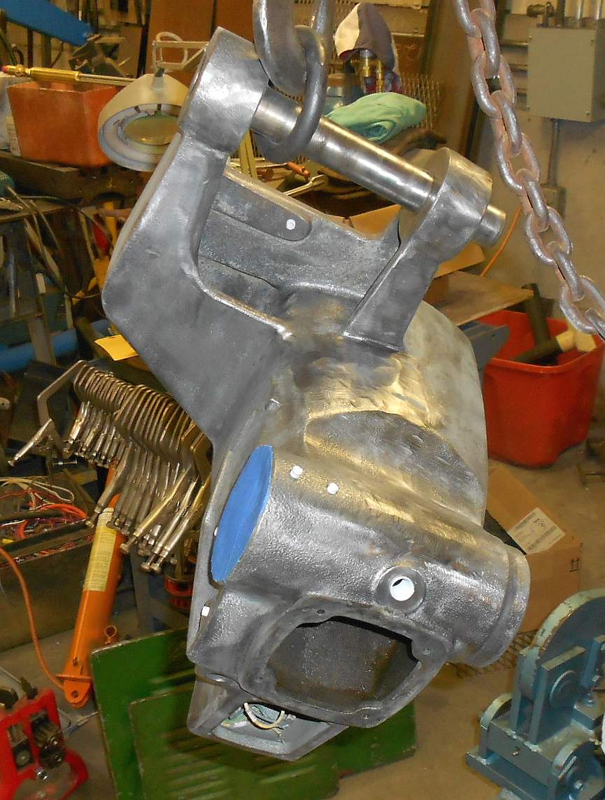
As I mentioned above, on this cold saw it is possible to set things up so that the saw blade cuts into one of the saw castings. This casting holds the saw's vise. I had already boiled this casting in a solution of dishwashing detergent, and run it through an electrolytic derusting bath. I could have just masked it and painted it but the scars really detracted cosmetically and I wouldn't have been happy.
So let me now tell the story of how I fixed the scars. Let's begin with a picture of the saw overcut scars:
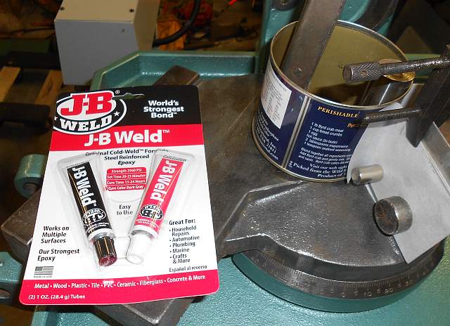
My strategy for repairing these scars was to form a mold around the original topology, and to fill the cut-away parts (the scars) with JB Weld, a metal-filled 2-part epoxy. My idea was to have the mold be made up of separate pieces each of which fit tightly to the casting below the scars, so that the JB Weld would run down and fill the voids but wouldn't run out the bottom. If you've ever worked with the original JB Weld you know that it will flow until it sets up. My strategy relied on this fluidity.
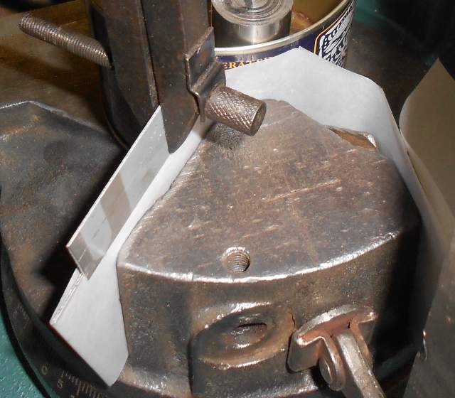
The first part of the shape to fit is the central curve, a cylindrical arc. After some searching, I found a can which closely fit the curve:
If you look carefully you can see how I ground away the seam for a portion of the bottom of the can so the can would fit more closely to the casting. I was pleased with how well the can fit.
There were two side pieces to my multi-part mold. I cut the material for these from some scrap aluminum sheet. It took a bit of handwork to make the bend and the edges all line up tightly against the casting and also tight against the can. Have a look:
As you can see, I secured the side plates with magnets. These proved to be plenty strong to resist the side pressure from the JB Weld.
I wanted the epoxy to stick strongly to the casting, but to not stick to my mold at all. I also wanted to ensure that no epoxy leaked out the seams between the side plates and the can. I borrowed some parchment paper from the kitchen, and lined the mold with a single piece. Parchment paper is impregnated with silicone. Nothing much sticks to it. Here is a picture of the mold all put together and ready to pour:
Here is the product I used, classic 24-hour J-B Weld:
I mixed the two-part epoxy on a playing card, using a piece of scrap sheet metal a bit bigger than a domino as a tool. I used the tool like a putty knife without a handle to tuck the filler down both sides. When I was done, I scraped off the tool on the playing card and just threw the playing card away. I was able to wipe the uncured JB Weld off of my tool to save it in case I needed it again. Here is a picture of the mold filled with uncured JB Weld:
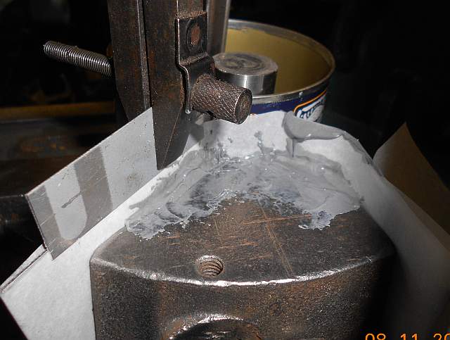
I was completely depending on the JB Weld's fluidity for it to run down and fill the crevices without any voids. I knew it would fill the side with the huge scars. The other side was much tighter, so it was a lot tougher to flow down into. In fact, the large side filled correctly but the epoxy didn't quite cover the lightly-scarred side.
After a few hours the epoxy had set up soft. It would take another 16 hours to cure fully after which it can be milled or sanded or filed as needed. I was happy when I removed the mold to see that indeed the parchment paper peeled easily away from the epoxy. Have a look:
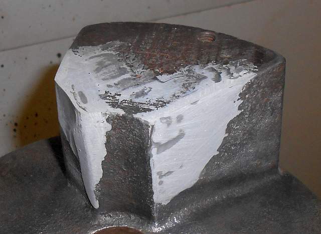
As you can see, the large scars are completely filled. The side next to the mold is smooth and straight and will need little cleanup. The next step was to sand the top and sides smooth.
Here is a picture which shows what the part looked like after sanding:
It was a little rough and frankly could have used another go or two putting on epoxy filler letting it dry and sanding. But I've been accused of trying to make a silk purse out of a sow's ear so I declared victory and moved on to masking and painting.
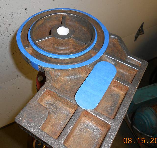
This particular part turned out to be exceptionally fiddly to mask, especially the bottom. This is a swivel casting so the machined boss needs to stay unpainted. But there are lots of cavities on the bottom side that really need paint. The Italians never bothered. No wonder Rome fell. :-) Anyway, I did the best I could. Here are a couple of shots of the part masked, top then bottom view:
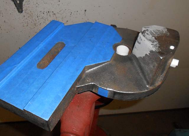
After I got the part masked, I went ahead and painted the top:
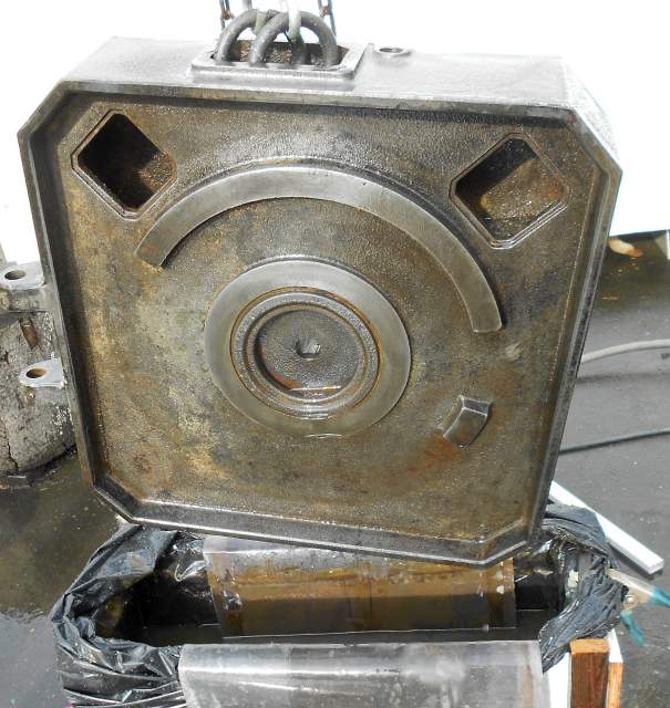
Please note, the paint is Hammerite, that's why it appears textured. But the area that was so badly scarred showed hardly any signs of damage after the repair.
With the saw base casting and its related parts completed, I decided to address the problem of the cold saw being very difficult to move. The machine's stand is made of sheet metal. The machine is quite top-heavy. This means skidding it even on a smooth floor is risky. I had quite a time trying to find a way to sling the machine so it could be lifted with a hook when I originally picked up the machine from the seller's shop. Also, the machine is not a tall machine. It appeared to have been designed for guys about 5'8" tall. Since I'm 6'1" tall, I felt the machine would work better for me raised a few inches. So I planned to make a rolling base for the machine to sit on. I had a nice piece of 1/2" plate just about the right size. Problem is it was warped. Worse, it was warped from corner to corner. It was curled up like a potato chip. I had a heck of a time figuring out how to straighten it. I tried heat shrinking with a torch. Didn't touch it. After much head scratching I came up with this:
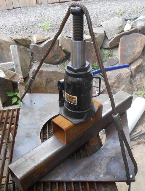
I used a 20 ton bottle jack and a steel cable to pull the corners up while pushing the other two corners down. It was easier to straighten because I cut out a large hole. This hole serves three purposes. First, it lets me get a hand up inside the machine base to put nuts on the caster mount bolts. Second, it lightens the rolling base, as all that steel isn't necessary. I saved the piece I cut out because it fits over the bolt holes in a truck brake drum. I like to use those to make freestanding machine pedestals. Anyway, as you can see, the plate is already drilled for casters. The casters were made by Aero and were a lucky find at a swap meet. They are extremely well made and were very expensive new. Now I can roll the machine around the shop and if I need to lift it I can run slings under the rolling base.
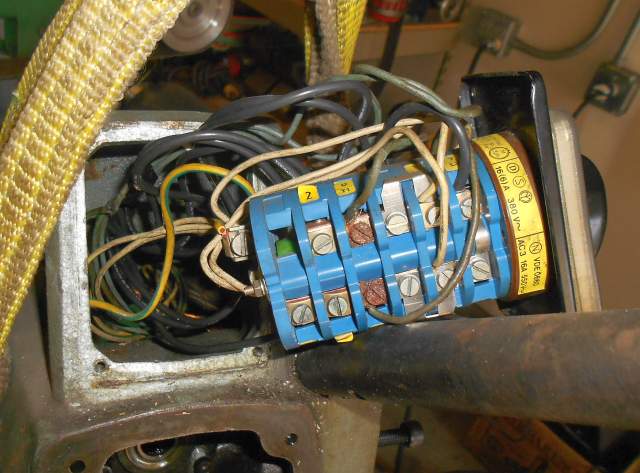
The moving problem resolved, I moved on to clean up the machine's power wiring. Without going into a lot of detail, I added three single phase transformers to the sheet metal machine base. Rather than bolting them to the outside of the machine, I decided to put them inside where the coolant and chips cannot reach them. I added a square junction box to the outside bottom of the sheet metal machine base. I gave the machine a nice long power cord made of 14SO4 cable with a proper three phase plug on it. This will plug right into my shop's three phase distribution system. I also added a small definite purpose contactor made by Square D. I had to fit the contactor with a 440V coil and the right heaters before putting it on the saw. So the wiring goes from the wall to the junction box to the contactor box up to the head. With the saw's sheet metal stand cleaned, painted, bolted to its new rolling base and with the new transformers and contactor installed and wired, the machine stand was now complete:

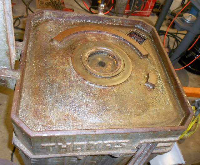
Because the piles of cleaned painted parts were, well, piling up, I put together what I'd done so far:
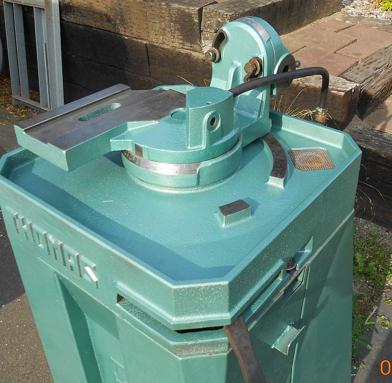
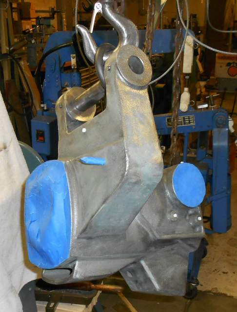
By the way, I polished the machined surfaces on the swivel castings using a 3M deburring wheel on a small electric motor. It did a great job. I stoned the slideways lightly and then gave them a coat of Johnson's Paste Wax. Whereas those castings would have needed a huge hammer to move them when I started, now they slide like they're on bearings. I can now pull on a lever, swivel the vise and head to wherever I like (swiveling about the vertical axis; the head also swivels in another axis) and push the lever back to lock it. This part of Thomas's machine design I quite like.
Next I disassembled the gearbox. Without an exploded parts diagram or manual for the machine, this was pretty much a white cane operation. I did eventually get it all apart and figured it all out. Remember above where I talked about how the gearboxes in Italian cold saws can go bad? This one was really trashed! However, it was well designed and all of the wear and damage was limited to one part, a bronze worm gear. That gear was so bad you could hardly see that there had once been teeth on it. Sadly, I don't have a picture of the old worn gear.
When I got to this point I went through the process of communicating with Thomas in Italy. I emailed them a picture of the saw and asked for a manual. They responded by asking me for the machine's model number and serial number from the nameplate. Well, my nameplate is missing. They then told me sorry, there is nothing they can do without that data. Very discouraged, I sent out an email to a few friends who knew about the project. I was about ready to throw the whole thing away. However, an amazing thing happened! First, one friend (Doug) told me that he used to own the saw and that he had purchased a replacement gear for it back in the '80s when he got the saw. He told me that it should have been with the saw, in the shop where it was being sold off. I went back to that shop and looked. No such gear. More black depression. Then a second miracle happened! A second buddy (Andy) wrote me that he bought a lot of miscellaneous metal from that same shop, and that there was a big bronze worm gear in the lot. I beat feet out to Andy's and got the gear, and brought it home. Lo and behold, it was the correct part! Considering the long and sketchy history of this machine, I found this to be absolutely astonishing!
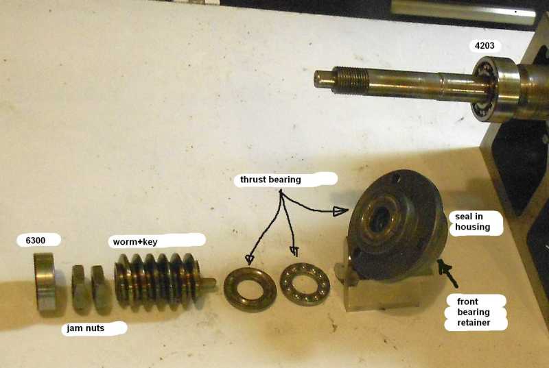
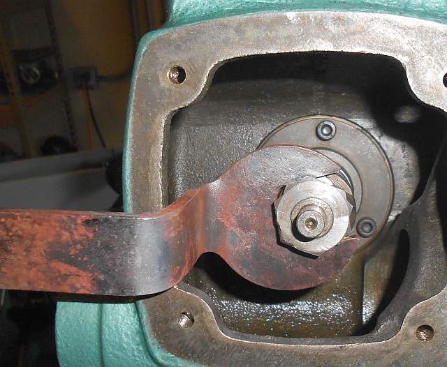
I did keep track of how the gearbox came apart. Let me digress. The head of this cold saw is very compact and it contains the motor built right in integral to the head. The motor's shaft extends into the gearbox. The gearbox's main shaft is at 90 degrees to the motor shaft. The motor shaft has a hardened steel worm which is located and secured by a thrust bearing behind the worm and two nuts in front of the worm. The big problem with this saw was that those two nuts had worked loose, so the worm was free to move back and forth on the motor shaft. This was why there was such extensive backlash in the saw blade. It also explained the amazing amount of wear on the bronze worm gear - the mating steel worm's moving around just destroyed the worm gear's teeth.
One further digression. I'll get back to the restoration soon, I promise! When I drained out the old gear oil, as I always do I took it up to the local auto parts store to recycle it. It's free and the responsible thing to do. The guy behind the counter looked at the old gear oil, heavily flecked with gold colored specks of bronze, and told me it was too contaminated to even go in their waste oil bin! Fortunately, the manager overheard and overruled him. Suffice it to say there was a LOT of metal flakes in the old gear oil.
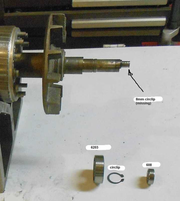
I did lay out the parts in a crude attempt to replace a proper exploded parts diagram. Have a look:
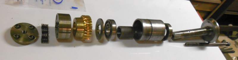
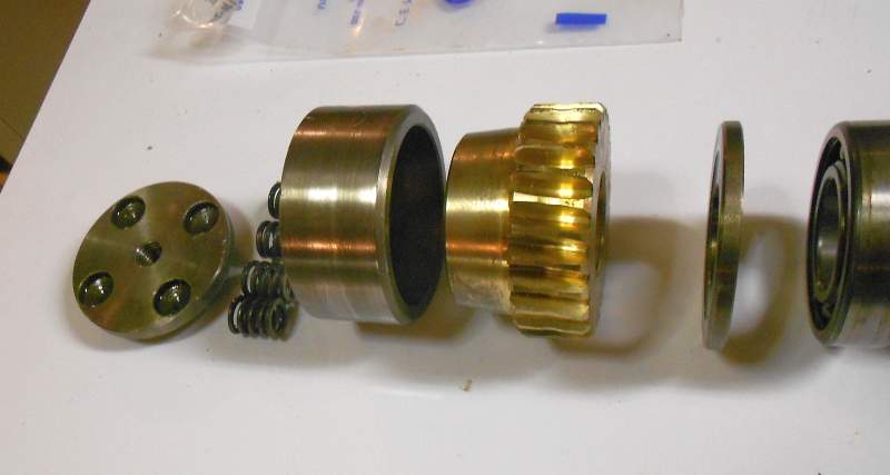
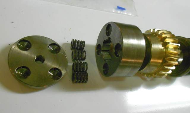
If you look closely at these last two pictures of how the saw's main shaft fittings go together, you can see that there is a steel piece which mates with the taper on the bronze worm gear. The steel piece is broached to fit the splines on its section of the main shaft. The steel clutch piece can slip axially. The worm gear, however, is not keyed to the shaft. If its male taper is pushed hard enough against the female taper on the steel clutch, the worm gear's rotation will turn the shaft. But if the saw blade jams, the clutch will slip keeping the damage to a minimum. The pressure is achieved with a plate screwed through the center of the main shaft. The plate has 4 counterbored holes which locate 4 beefy little springs which press against the steel clutch. The picture shows 4 matched little springs. When I took the gearbox apart, though, there were 3 matching springs and one really oddball spring. With no parts available, I just ordered new springs from a spring manufacturer. I wasn't able to get an exact match but these springs are quite close to the originals and in fact work fine. Here is an image of the rebuilt saw spindle:
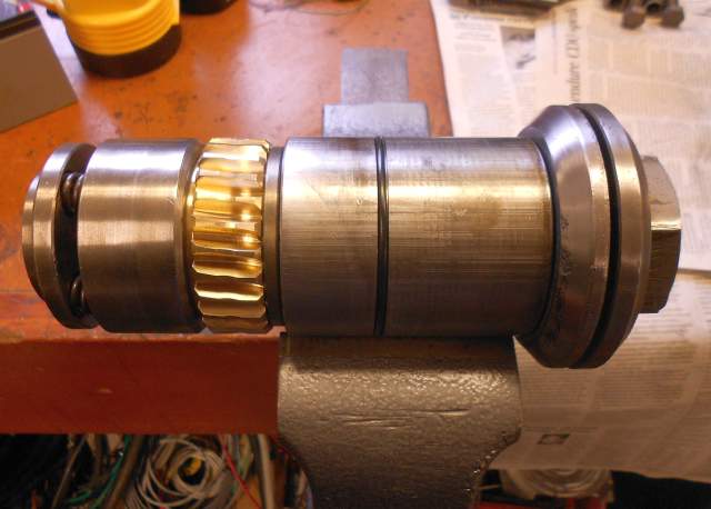
Here are my "exploded parts" shots of the motor shaft:
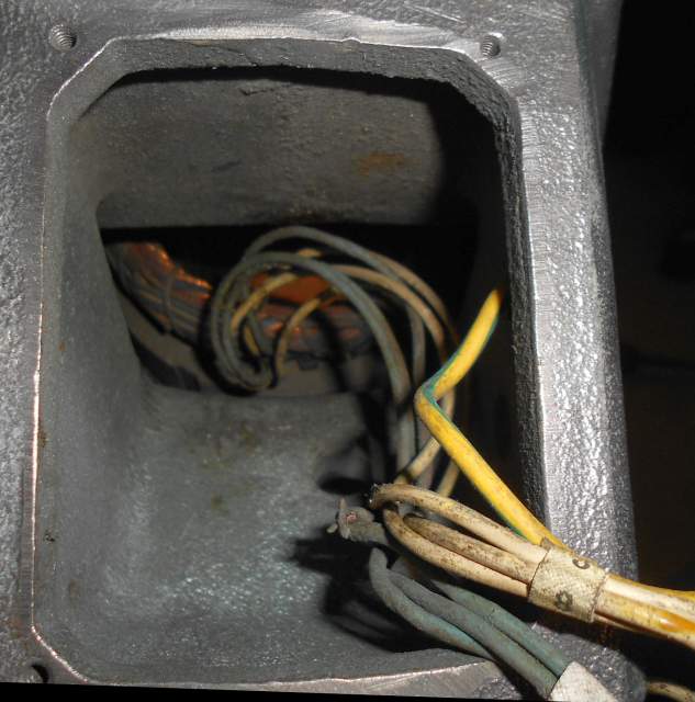
With the motor all torn down, it only made sense to replace the bearings. I wound up replacing all of them except the thrust bearing behind the steel worm. I would have bought a new one of those too except it had no markings and was too hard to source. So with all new bearings, the saw motor was almost rebuilt. I found another big problem with the saw when I looked closely at the motor wiring, however. The motor on this Thomas cold saw is a two speed constant horsepower motor. It has two bundles of three wires that come from the stator windings up to the switch cavity in the saw head. The insulation on one of these bundles was very badly cracked to the point where the strands inside were exposed. On two of those wires most of the strands had frayed to the point where they weren't connected any more. If the saw had been run much longer, one of those wires would have completely come apart and the saw motor would have burned out. Again, a stroke of blind luck - I had caught the problem in time. With my buddy Andy's help, we cut out the bad wires and spliced on new ones with two layers of heat shrink covering the splices. I followed that up by wire-tying the bundles in such a way that they could never foul on the rotor segments, which is what we figured damaged the wiring in the first place. With new bearings and repaired wiring I could now consider the saw's motor to be rebuilt. I do have one picture of the old damaged motor wiring. The white bundle is the one with damaged wires.
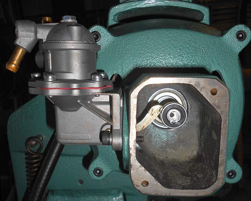
At the very rear end of the motor shaft, there is an eccentric machined onto the shaft. This eccentric holds a roller skate 608 bearing which acts as a follower and bears against the arm of an automotive fuel pump which this saw uses as a coolant pump. I've heard that these pumps were made by Fiat. But my buddy Doug told me that a former owner put an old Ford fuel pump on it. Since there was nothing wrong with the pump, I never took it apart so I don't know who made it. But it works great for pumping coolant fluid out of the sump and over the cut. It runs down onto the saw base and through screens back into the sump. This is how the back of the saw head looks with the cover plate removed:
I'm getting ahead of myself here. At any rate, after I finished with the lower end of the saw, and after removing the motor's rotor and rear bell and removing the contents of the gearbox and wheel guards and handles I moved on to the head casting itself. Since it has the motor's stator in it, it could not go into a hot degreasing tank or a derusting bath. I chose to hang it up on my shop's overhead crane and just cleaned it as best I could with a wire wheel plus shop solvents and rags. As a side note, the wire wheel removed whatever shreds were left of the motor label. Now my machine has no nameplates of any kind. See:
If you look closely you will see I rolled up little pieces of paper and stuck them partway into threaded holes, then let the paper unroll. Tiny rubber plugs work better but I don't have any so I just use paper. Everyone has paper, right? At any rate, with the head casting cleaned up I painted it.
There were a couple of small side fixes needed. For example, this saw is basically a chop saw. You reach up and grasp the handle, squeezing a lever, then pull down. The lever is coupled to a cable which is made identically to old motorcycle cable. It goes to a sheet metal box which fits deftly on top of the head, and actuates a switch in there. The switch is wired to the motor's coil in "jog" configuration. Pull the switch and the motor runs. Let go and the motor stops. Very simple. Only the control cable's jacket was really old and cracked in several places. A trip to the local motorcycle shop provided me with a new length of cable sheathing. I was able to reuse the wire cable itself as well as the sheath end fittings. Now the cable is like new again and should last another 50 years or so.
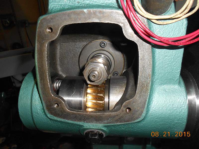
After the head casting paint dried, I reassembled the top end of the saw. There is a biggish spring on the back which is about like a small version of a garage door spring. I kept the old spring, still in serviceable condition. With the head mounted back on the saw, I reassembled the motor and gearbox. Here is a picture of the assembled gearbox looking through the hole where the cover plate goes.
See the two nuts on the motor shaft? Those nuts came loose before - that caused one of the saw's biggest problems. I can see why the last guy in here had trouble tightening it. There isn't anything to tighten against. Turn the nut to tighten it and the rotor just turns on its bearings. You can get it kind of tight but not properly tight. So I made a special wrench:
With that wrench in one hand holding the rear nut and a socket wrench in the other hand over the front nut, I can jam the nuts against each other tightly, thus holding just the right amount (a few thousandths) tolerance but not coming loose. Once I was done with the special wrench I stuck it to the inside of the machine's sheet metal base with a magnet in case I ever need it again.
During the saw head reassembly, I had to rewire the motor switch wiring. This isn't the switch you squeeze. Rather, it selects between low speed, off, or high speed. (Remember, the saw has a two-speed motor.) Here is what the wiring originally looked like:
Again, I had no manual. Thus no switch wiring diagram. I had to figure out all of the motor wiring from scratch. It turns out to have Dahlander windings. I carefully documented everything and made new labels for the wires and the switch connections. Didn't take a picture of it, though, sorry!
The motor/gearbox reassembly went smoothly. I got it all together, plugged it in, turned the switch to low, and squeezed the handle switch. It started and immediately jammed. Oh, no! More dark thoughts about scrapping the whole machine. I can't believe how ready my mind is to throw away months worth of work and hundreds of dollars. Anyway, I tore the gearbox apart and pulled the rotor again and carefully checked the shaft for bending. Nothing. Is something cocked on the install? No, everything's solid, square, tight, right. I'm going to skip a couple of days worth of anguishing torment and just tell you right straight out what the problem was.
Back on the motor shaft as it extends into the gearbox. There is a worm keyed to the shaft, free to slide axially. There is a 3-part thrust bearing behind it, and 2 nuts outboard of it. When I really really looked at the 3-part thrust bearing I discovered that the two outer parts were different! Their outside diameters were identical but one is a press fit over the shaft on the ID and the other's ID is a few thousandths larger to let the shaft rotate freely inside it. The one with the larger bore is supposed to be pressed into the bearing retainer which is bolted to the head. Well, I got them backwards. So the shaft was a press fit to the ID of the thrust washer's end plate and that same plate was a press fit to the head. Ergo, jam. Train wreck. The fix was simple: swap the washers.
Big sigh of relief. Now the motor runs! With no more drama I put the rest of the saw back together. The coolant hoses and filter all went together fine. The wheel guard and outboard stock support arm cleaned up fine and went back on just right. Yay! It's done finally!
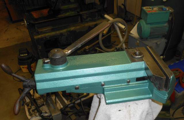
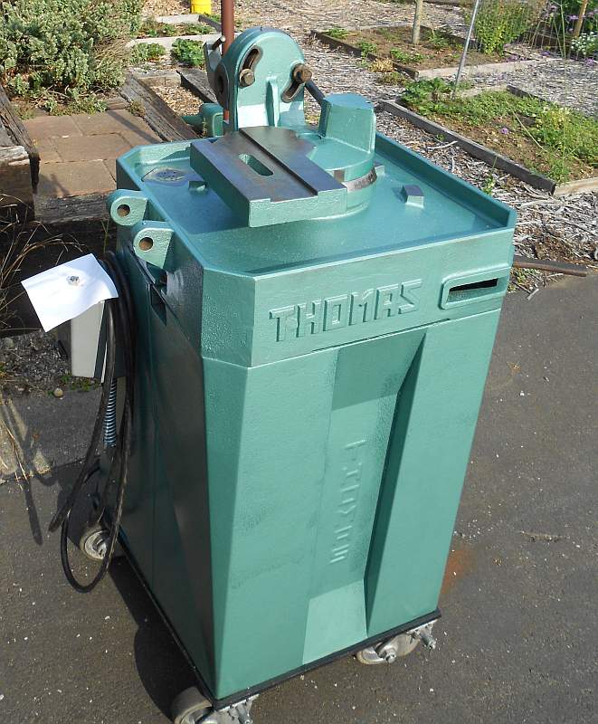
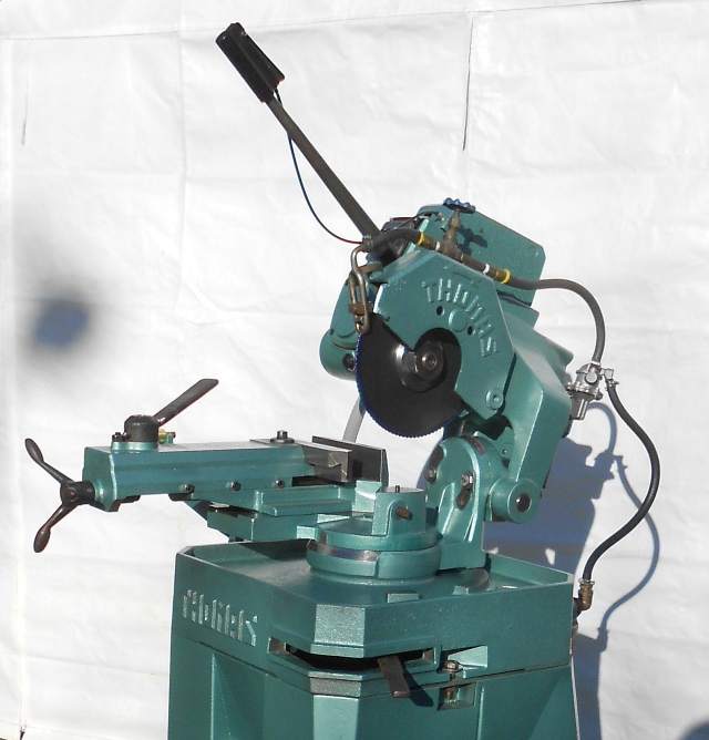
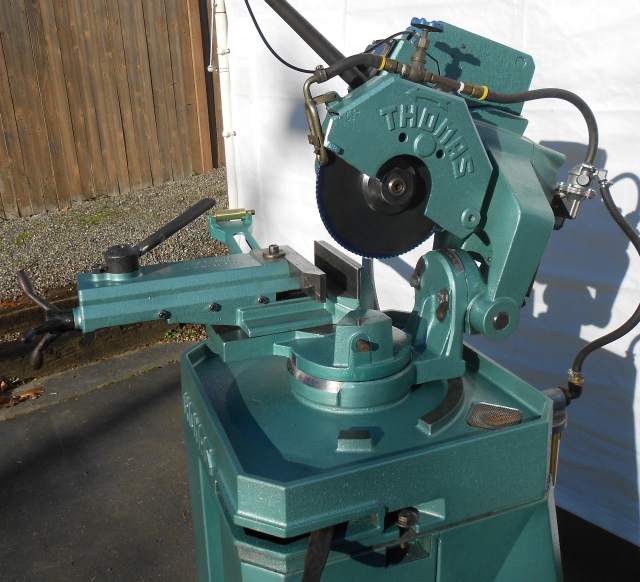
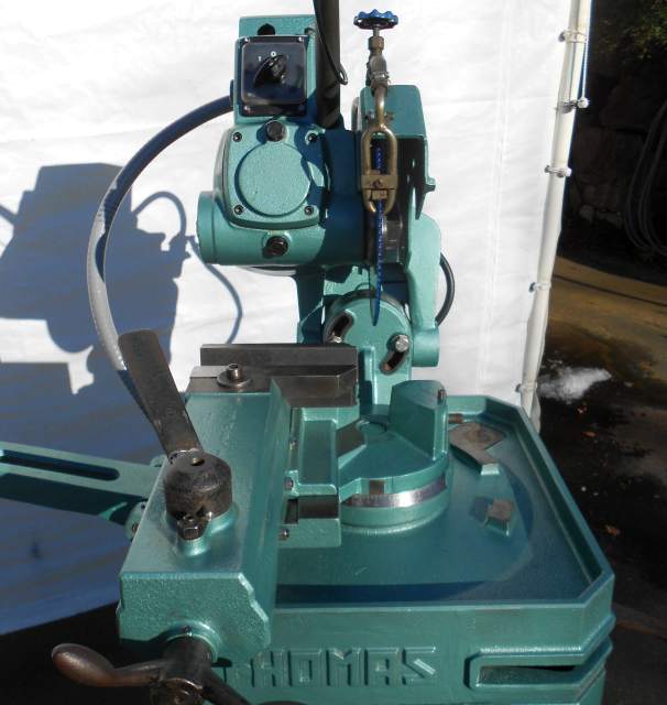
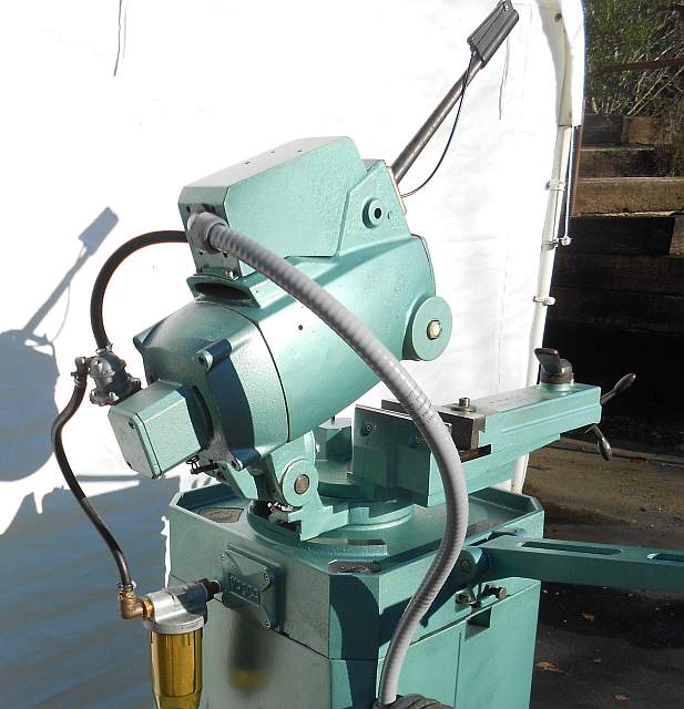
Just so you can compare, here are 'before' and 'after' photos:
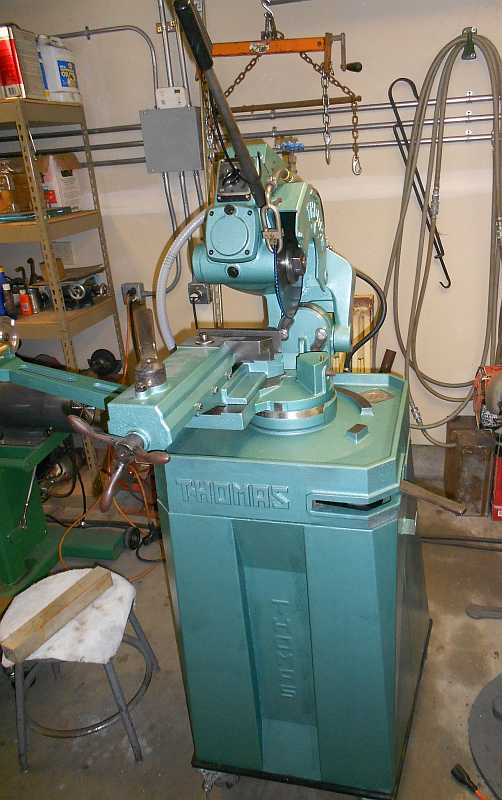
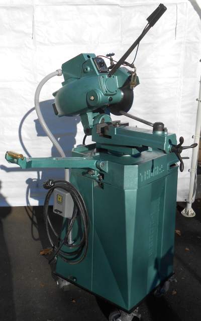
Completed pictures:
Since this machine has no nameplates, it has no model number nor serial number. Therefore Thomas cannot provide me with a manual. If you google on "Thomas cold saw" and look at the images you can see many saws that look sort of like mine, but none with the saw blade to the right of the handle. If you ever do run across one, I would really welcome a sharply-focused closeup picture of the machine's nameplate. Not the motor nameplate. Not the one with the volts and amps on it. I need the one with the model number on it. If you can find one, please email it to me at grant AT nwnative DOT us and I will be eternally grateful.
I used Mobil SHC640 oil in the gearcase. One quart was plenty. I bought two soluble oils to try; Trim-Sol and Trim-EP. I don't know if either is the 'right' soluble oil to use to make up flood coolant.
Thank you for reading this!